Home My New Layout Diagram of My  Layout My OLD Layout LV & WR MRRC Scenery Work C&O Berkshire &
Live Trains
CTC How-To Lesson

CTC Wiring

(Centralized Traffic Control)

Understanding the system.
HO Trains run on DC power. DC stands for direct current... that means like a battery.
In DC circuits, the electrons (the electricity) flows one direction only: from positive to negative (
+ to -). Place yourself in the cab of your engine, looking out the front window.
To make your HO train move forward, you must connect + to the right rail and - to the left rail. Forget about inner/outer rails - think right and left only.
Direction Reversing Loops.
The challenge with a loop is to prevent crossing the + and - connections and to never have to flip the forward-reverse switch on your cab control (power pack).

* * * * * * * * * * * NOTE* * * * * * * * * * *
Throughout this project, you can always click on any drawing to see the full size (and usually larger) version of the picture in a new window.
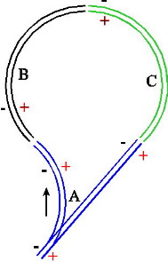
Assume the examples, below, are shown with North up. As the engine enters the loop on the blue section (A), + is on the right rail. As the engine enters travels North into the black section (B), + is still on the right rail and again as it heads East into the green section (C). The problem occurs as you try to leave the green section (C) (heading South now). In the blue section (A), + is now on the LEFT!, not the right. You have to be able to reverse (switch) the + and - connections on the blue section to finish the loop and the direction change.
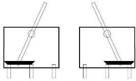
Entering the loop.

Through the loop.

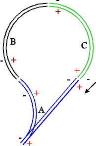
No CTC - can't exit the loop.

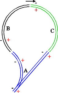
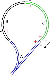
With CTC - switching the direction.
You simply need to reverse the blue section while traveling over the black and green sections. (Once you clear the blue section, on the way into the loop, you can flip the direction switch for section A and it will be reversed and ready when the train heads back out of the loop.) Now, all we have to do is control how we keep + on the right and - on the left when we reverse directions on a section of track. This function is accomplished with one toggle switch for each section of the layout. It requires a simple DPDT toggle switch. DPDT = double pole - double throw (like two - 2 position switches combined). Click here to see an animation of the procedure.

Diagram 1
Switch basics. Switches are described by poles and throws. The # of poles refers to the seperate circuits in the switch. The # of throws refers to how many positions it can can make contact at (not including the off position). The simplest switch is the SPST switch like the knife switch (diagram 1). Your common light switches in your house are simple SPST (single pole single throw) switches used to either open or close a single circuit. It has two positions but makes contact at ONLY ONE position - the ON position (single throw). This is called Off-On.
The # of poles refers to the number of circuits (or paths) that can run through the switch. With a knife switch, the pole is the lever on the pivot point. When the SPST switch is open, as shown in diagram 2, it 'breaks' the circuit (like breaking the wire to stop the current flow). Once you close the switch, current flows (electrons flow) through the completed loop from the + side of the battery (top), through the closed switch, through the light, and back to the - side of the battery.

Diagram 4
The SPDT knife switch (diagram 4) can connect the center pole contact to the left, the right, or remain off (in between).
When the SPDT switch is in position A, as shown in diagram 3, current flows through the completed loop from the + side of the battery (top), through the common terminal (pole) of the switch, through contact A, through light A, and back to the - side of the battery.

When the switch is moved to position B, current flows through the completed loop from the + side of the battery, through the common terminal (pole) of the switch, through contact B, through light B, and back to the - side of the battery.


A SPDT switch.
This is a side view of a typical SPDT switch (cut-away view).
Notice that the CENTER & LEFT contacts close when the lever (protruding from the top of the switch) is pushed to the RIGHT. Likewise, the CENTER & RIGHT contacts close when the lever is pushed to the LEFT.
The center contact is called the COMMON contact - the contact common to both positions. You can learn more about switch (& circuit) basics here and here.
Click here for a larger picture.
A miniature DPDT switch.
A DPDT switch is like 'gluing' two SPDT switches side-to-side to make one unit which works on a single lever. Likewise, a 3PDT (3 pole - double throw) switch is like three SPDT switches 'ganged together'. To change the engine direction, you have to control the wires to both sides of the track plus you need an OFF position too: DPDT On-Off-On switches. It is also critical that it can handle the current pull expected so use at least 2 amp (2A) switches. (DPDT On-Off-On switches with 2A contact ratings.) I suggest about 4A - 5A switches for long, dependable life.

Now you're ready to start wiring the switches to perform 'magic' and give you real control of your trains. Click here to go to the next page and learn about CTC direction wiring.