Home My New Layout Diagram of My  Layout My OLD Layout LV & WR MRRC Scenery Work C&O Berkshire &
Live Trains
CTC How-To Lesson

(Centralized Traffic Control)

This addition is very complex in operation so about all I will do here is explain the wiring: very little about the theory of operation. I will, however, refer to pages to explain areas I skip so you can visit them if you want to learn / understand more about how the display works.
Here's a drawing of what your swicthes and displays should end up looking like. Diagram 24 shows the Cab control switch in position 2 and the display clearly indicates CAB 2 is running this section of track. The direction control switch is thrown to the left (West) and the green LED lights up in the left arrow. A quick glance at the indicators (all in a single spot) gives a clear indication that Cab 2 is controlling this section of track and heading West.
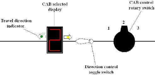
 Click for a larger diagram.
Diagram 24
Click for a larger diagram.
Diagram 25
Here's a drawing (above) of what a sample of a CTC would look like for sections A, B, & C. The round-red buttons are used to control the track switching (throw the turnoutrs on the track). Diagram 25 shows the following:
CAB #2 is controlling the inside tracks of all 3 sections and traveling clockwise. (2 on the displays and green LEDs lit.)
CAB #3 is controlling the outside tracks of all 3 sections and traveling counter-clockwise. (3 on the displays and yellow LEDs lit.)
The middle track in section B is turned OFF. (All indicators off.)

This area not yet complete but it will be before long.